
There are a lot of dearly held beliefs about strobes out there, but let me try to dispel the myths and the mysteries.
Yes there is. Here is the formula. It can be off by as much as a stop because not all strobe zoom lenses are equal.
|
|
where E is the watt-seconds stored in the capacitor, and EFL is the effective focal length of the lens. (For a full frame 35 mm camera.)
For engineering Geeks: This page gives the set of assumptions and how the above formula was calculated.
Here is a table of Guide Numbers for a number of photographic strobes with different focal length settings at ISO 100.
| Model | Energy in Watt-Seconds | 18mm | 24mm | 35mm | 50mm | 85mm | 105mm | 200mm | |||||||
| meters | feet | meters | feet | meters | feet | meters | feet | meters | feet | meters | feet | meters | feet | ||
| 1970 Rolei | 18 | 17 | 56 | ||||||||||||
| Nikon SB-300 |
20 | 18 | 59 | ||||||||||||
| 1971 Prinz | 26 | 20 | 66 | 24 | 79 | ||||||||||
| Metz M24 | 36 | 24 | 79 | ||||||||||||
| Nikon SB-500 |
36 | 24 | 79 | ||||||||||||
| Metz M36AF | 36 | 20 | 66 | 24 | 79 | 30 | 98 | 36 | 118 | ||||||
| Sunpak PZ42X |
36 | 24 | 79 | 42 | 138 | ||||||||||
| Canon 430EX | 38 | 24.5 | 81 | 43 | 141 | ||||||||||
| Metz M44 | 40 | 25.4 | 83 | 44 | 144 | ||||||||||
| Honeywell Hieland Strobanar 64 | 45 | 21 | 70 | ||||||||||||
| Nikon SB-700 |
49 | 28 | 92 | ||||||||||||
| Spiratone StrobeMaster | 50 | 24 | 80 | ||||||||||||
| Canon 320EX | 52 | 24 | 79 | 27 | 88 | 32 | 105 | ||||||||
| Metz M50 | 52 | 27 | 88 | 50 | 164 | ||||||||||
| 1985 Focal | 60 | 25.3 | 83 | 30.5 | 102 | 32 | 105 | 36 | 118 | ||||||
| Metz 58AF | 72 | 28 | 92 | 34 | 112 | 40 | 131 | 46 | 151 | 54 | 177 | ||||
| Nissan Di866 | 73 | 20 | 66 | 27 | 88 | 34 | 112 | 37 | 121 | 39 | 128 | ||||
| Nikon SB-910 |
73 | 34 | 112 | ||||||||||||
| Canon 600EX | 74 | 26 | 85 | 35 | 115 | 60 | 170 | ||||||||
| Nikon SB-800 | 82 | 18 | 29 | 95 | 36 | 118 | 38 | 125 | 45 | 148 | |||||
| YongNu YN565EX | 85 | 15 | 49 | 28 | 92 | 39 | 128 | 42 | 138 | 53 | 174 | 58 | 190 | ||
| Canon 580EX | 85 | 15 | 49 | 28 | 92 | 36 | 118 | 42 | 138 | 53 | 174 | 58 | 190 | ||
| Nissin 4500GTE | 130 | 45 | 148 | ||||||||||||
I have also plotted several commercially available photographic flash guns as symbols to see how they fare against the formula. Please note that this is a log-log scale.
The top dark blue line represents a very aggressively focused flash gun set for a 135 mm focal length lens. This is a modest telephoto lens. There are a few flashguns with this capability and some are shown as circles on the plot, with Guide Numbers from 45 to 55.
The gold curve is for 85 mm EFL lenses. The black curve is for 50 mm EFL lenses.
35 mm is the normal "design to" focal length, and most strobes unless otherwise specified are rated for a 35 mm focal length lens. Along this curve, you can see built-in flashes and flashes in disposable cameras are shown in the light yellow shaded area, having guide numbers from about 10 to 14.
The orange area represents low cost flash guns with guide numbers up to about 20 or so.
The pink area represents small flash guns, but possibly with a number of features such as adjustable field of view, and possibly IGBT (see below) circuitry.
The green area represents premium flash guns with guide numbers around 30 at 35mm and up to 60 at 125 mm focal length.
The light turquoise colored area is the area occupied by the "potato masher" flash gun. I happen to have a Nissin 4500GTE, so I plotted it on the graph.
 In
1970 I got an SLR 35mm camera (Ricoh) and an electronic flash (Prinz.) Two years
later I was aware that the strobe was bad for my camera's contacts (more about
this later) so I modified it with an LASCR across the sync contacts, which not
only saved the contacts in the camera, but also made the unit into a slave
flash. This unit stored about 13 watt-seconds, or joules when the ready light
came on and eventually came to a full charge at 26 joules. The Guide number in
feet for ASA 64 film was 64. In the process I reverse-engineered the strobe. I
don't have a picture of this strobe that I know of, so I found a similar model
online for the picture.
In
1970 I got an SLR 35mm camera (Ricoh) and an electronic flash (Prinz.) Two years
later I was aware that the strobe was bad for my camera's contacts (more about
this later) so I modified it with an LASCR across the sync contacts, which not
only saved the contacts in the camera, but also made the unit into a slave
flash. This unit stored about 13 watt-seconds, or joules when the ready light
came on and eventually came to a full charge at 26 joules. The Guide number in
feet for ASA 64 film was 64. In the process I reverse-engineered the strobe. I
don't have a picture of this strobe that I know of, so I found a similar model
online for the picture.

About that time, I bought a Rolei flash. It has three features. It was very small and light. It had a hot shoe. It had auto exposure (via a quench tube.) It reached a grand total of 9 joules at full charge.
About then, the buzz in flash photography
was the auto-thyristor flash. A thyristor is the generic name given to SCRs,
Triacs, and Quadracs. Being a struggling college student, I could not justify
buying one of the new energy conserving flashes. By luck, Honeywell, who had a
few years earlier invented auto-exposure flash photography, had run into a lot
of competition. I was able to acquire several boards capacitors, reflectors and
sensors from a surplus parts sale. I reversed engineered the units and built an
auto flash.


Eventually, the inability to aim the flash separately from the sensor was
limiting for bounce flash. I bought a unit from Spiratone called a Strobemaster.
I actually still have this unit, but the battery holder contacts eventually
broke from the stress of putting batteries in it all the time. I should probably
say that Spiratone was able to repair my unit for a reasonable price after the
hot shoe connector was damaged when it when through a loop-the-loop amusement
park ride attached to the camera. I sometimes was unhappy with Spiratone, but
they were quite reaonable with this flash.


I next bought a unit from Kmart which was auto thyristor and had a zoom
fresnel lens to adjust the spread angle.


Next I bought a Nissin 4500gte potato masher. It has everything including a safe trigger circuit compatible with modern cameras. It also has about 4 times the power of my earlier flash units. I also have several studio flash units which run on 110 volts. With all of the reverse engineering, I thought I would share a little about how these puppies work.

My most recent flashgun is a Yongnuo YN-565EX.
My flash guns
| Year | Flash Model | Auto | Thyristor | Vertical Bounce | Zoom | Horizontal Bounce | Synch | Energy | Guide Num ft/m |
| 1970 | Prinz Universal Tri-light | full trigger current | 30 J | 80/24 at EFL=50mm |
|||||
| 1973 | Rolei | X | full trigger current | 22 J | 56/17 | ||||
| 1977 | Spiratone Stobemaster | X | X | X | full trigger current | 50 J | 80/24 | ||
| 1984 | Focal DT-600 | X | X | X | X | full trigger current | 60 J | 90/27 | |
| 2002 | Nissin 4500gte | X | X | X | partial | X | 5 volts | 120 J | 148/45 |
| 2012 | Yongnuo YN-565EX | X | X | X | X | X | ETTL, remote | 80 J | 115/35 |
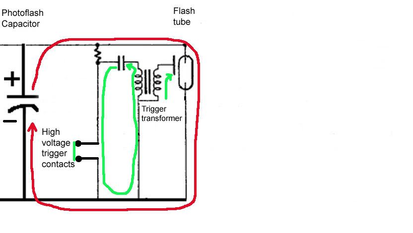
I have mentioned the energy for a strobe being stored in a capacitor. Let's take a look at the simplest possible strobe circuit.

Here we have a 300-500 volt battery as a power supply which charges up C1 when the power switch is turned on. The Xenon lamp is connected directly to the C1, which is charged up to 300 volts. No the lamp does not light up. Why? Because 300 volts is not enough to start the discharge and light off the lamp.
Instead, the xenon gas needs to be ionized first. This is accomplished with a 5000 volt pulse outside the tube. Notice that C2 charges up slowly to about 200 volts (R2/R3 make a voltage divider that leaves 200 volts at their junction.) When the camera shutter sync contact is made, the energy in C2 (about 2 millijoules) rushes through the transformer terminals 1 and 4, causing a large voltage at terminal 5 which ionizes the xenon gas. This allows C1 to discharge through the xenon lamp. Once the lamp starts conducting, its impedance is about 2 ohms, but it changes in a complicate way with voltage so that more current flows at lower voltage. The "negative resistance slope" makes gas discharge lamps unstable, requiring a ballast for steady-state operation. Since all we want is a pulse of light, we do not need to be concerned about this.
So there you have it. The simplest possible photographic flash. This is pretty much what you got when you bought an electronic flash in the 1960s.
After a little thought, you will probably notice several things that are not essential, but make the flash unit much more user friendly. Let's try to point these out one at a time, and show solutions to these inconveniences.
When the power switch is thrown, the unit is not ready to operate immediately. For one thing, C2 must be charged up through some relatively high resistance. So we wish to have a ready light come on when C2 should be charged up. This is what the circuit looks like:

R4 and R4 form a voltage divider so that as C1 charges, the voltage on the neon bulb increases. The neon bulb requires about 90 volts to fire, so the voltage on C1 must be at least 120 volts for the neon bulb to be lit. Obviously this is not a full charge, but in this case, it is enough to fire the strobe. This is why many photographers will wait several seconds after the ready light comes on to use the strobe. A ready light does not mean a full charge.
For reference, here is the reverse engineered circuit of my very first flash, the Prinz Universal Tri-light.

If you ignore the battery and the transistor circuit, looking at only the 110V AC input, it is very similar to the circuits we have already seen. It has a two transistor oscillator (they are completely wired in parallel, so one larger transistor would have worked) with a step up transformer to generate the 300-350 volts needed to fire the flash tube.
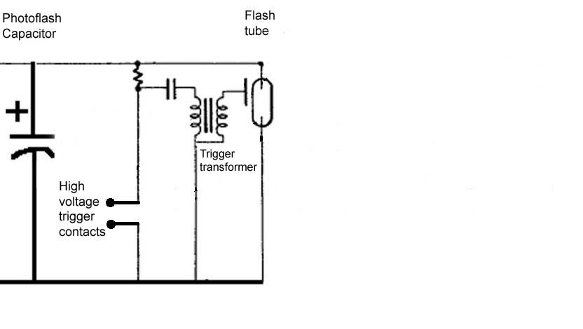
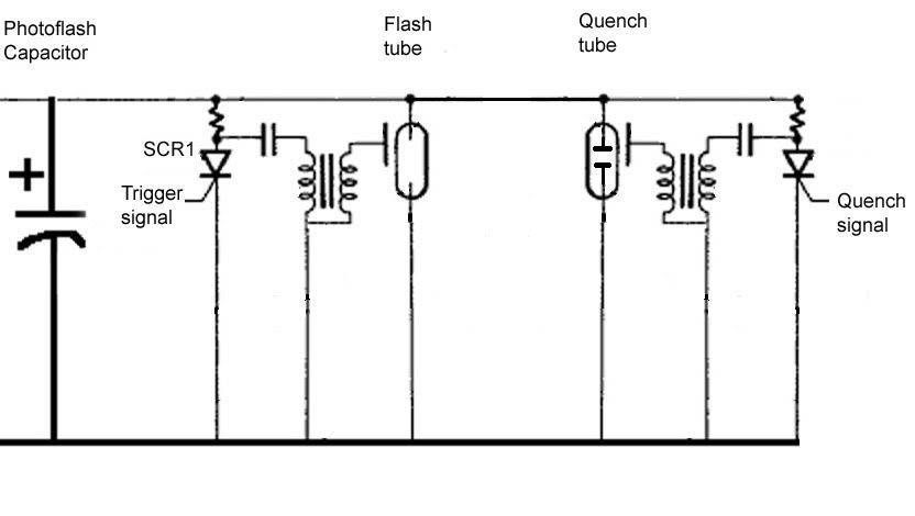
Our strobe so far dumps nearly all available energy from C1 through the xenon tube. Suppose that this is too much light for the exposure. What does the photographer do? The only compensation that a photographer could use was to change the aperture stop to control the exposure. This generally precluded a bounced flash shot with any accuracy. So what if we point a sensor at the subject, but allow the flash to be pointed at a ceiling of a wall? We could get an auto exposure if the flash gets turned off as soon as enough light is received at the sensor. This was first accomplished with a quench tube:

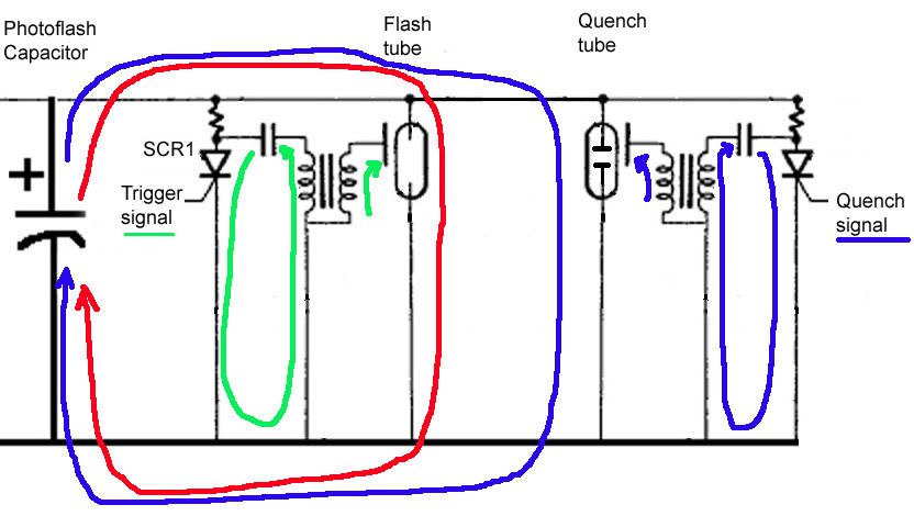
The quench tube circuit looks complicated, but it really isn't. It operates very much like the xenon tube, but it has a lower impedance, so when it fires, most of the remaining energy in the main capacitor is diverted to the quench tube, depriving the xenon tube of any more energy. The quench tube is triggered just like the xenon tube, with a high voltage pulse from XFR2. The energy pulse comes from C6, and is driven by the CdS photocell. When the gate of the SCR is low enough, the SCR fires and sends the pulse through the transformer. But what are the extra resistors and capacitors for?
Remember, out trigger circuit has to work while the main tube is flashing. How much current is flowing? Well 300 volts through 2 ohms is about 150 amperes. That is a lot of current, so the ground in the strobe circuit is actually a number of volts above the normal ground level while all of the current is flowing. Therefore, we have to isolate the quench tube trigger circuitry from the normal ground to keep the pulse voltage from interfering with its operation.
Let's look at an actual circuit from about 1970.
My little Rolei's circuit is shown here:

We now have the essential elements of a fully functional flash. (We'll get to the modern flash with all of its power options, remote triggering and TTL in a moment.)

Let's briefly talk about some of the deficiencies in our circuit so far.

We will address these deficiencies by improvements in their associated circuits.
I am a bit lazy so I am going to borrow some graphics that others have posted on the web. Here is a power supply represented in text form (a bit hard to read, but you can do it.)
                                                                       J2-2
                                             +--------------------------o HV+---+-----------------------------
                                             |  S2 Flash +-----------+          |      R4
      P1-1  S1 Power            o  T1        | Intensity |     R2    |          +----/\/\-----+---+
   BT- o---+---/ --+-------------+     o     |      High o   330,2W  |               4.3M     |   |
           |       |              ):: +------+-+-------+->o---/\/\---+                        /  +++ IL1
           |       /        D 15T )::(         |   Low | o     R3    |            Ready R5 +->\  |o| NE2
           |    R1 \          #20 )::(         |       +--+---/\/\---+             Cal. 5M |  /  |o| Ready
           |   150 /   +---------+ ::(         |          |  10K,1W  |                     |  \  +++
           |       \   |           ::( O 1950T |          |          |               R6    |  |   |
           |       |   |        o  ::( #46     |      C2 _|_     C3 _|_         +---/\/\---+--+---+
           |-      +---|---------+ ::(         |   260uF ---  260uF ---         |
     BT1   _       |   |          )::(         |    350V  |    350V  |          |
    2.4V  ___      |   |    F 15T )::(    D1   |    D2    |          | J2-1     |
    Sub-C  _       |   |      #30 ):: +---|<|--|-+--|<|---+----------+--o HV- --+--------------
     NiCd ___      |   |     +---+       BAY90 | | BAY90
           |+      |   |  Q1 |                 | |
           |       |  C \|   |                 | |
           |   C1 _|_    |---+                 | |  O = Output
           | 47uF --- E /| AD136               | |  D = Drive
           |  10V  |   |   (PNP)               | |  F = Feedback
           |       |   |                       | |
      P1-2 |       |   |                       | |
 COM  o----+-------+---+-----------------------+ |
                                                 |
      P1-3                                       |
 CCAC o------------------------------------------+

Reference
                   AC   D3
               +-o IN o-|>|--+
      S1       |             |
    DC  AC     |      D1     |X D2                                   Flashlamp
  +--o  o +-o  o +----|>|----+--|>|--+----------+-------+-------------------+
  |    /..|.. /  |           |       |          |       |               FL1 |
  |   |  +|  |   |           | LT1   +          |       |                   |
  |   |  ___ +---|------+   +++   ::(           \       \                  +|
  |   |   _      |      |   |o|   ::( L1        / R5    / R3               _|_
  |   |  ___ BT1 |      |   |o|   ::(           \ 1.2M  \ 3.3M            | | |
  |   |   _  9V  |      |   +++   ::(           /       /       Trigger  ||   |
  |   |  -|      |  C3  |    |       +          |       |                ||   |
  |   +---+ T1 +-+--||--+    |       |          |       |  C2      T2 +--||   |
  |         ::(3    220 |    \ R2    |          |       +--||--+   ::(   ||   |
  +-------+ ::(     pF  |    / 1,2M  | Energy   |       | .047 |   ::(   || _ |
  |       2)::( 118     |    \       | Storage  |       |  uF  +-+ ::(    |_|_|
  | R1 <.1 )::(         |    |       | 380 uF   | Ready |         )::(      |
  / 4.7K   ):: +---+    |    |      +| 350 V   +++      | Shutter )::(      |
  \    +--+ ::(5   |    +----+     __|__       |o| IL1   |-       )::(     -|
  /    |  4 ::( .2 |         |     _____ C1    |o|      | S2   +-+    +-+   |
  |    |       +--------+    |       |         +++      |      |        |   |
  |  |/ C      1   |    |    |      -|          |       +------+--+-----+   |
  +--|    Q1       |    |    |       |          |       |         |         |
  |  |\ E 2SB324   |  +_|_C4 |       |          |       / R4     _|_ C5     |
  |    |           |   ___   |       |          |       \ 3.3M   --- 100 pF |
  +----|-----------+  - | 10 |       |          |       /         |         |
       |  Inverter      | uF |Y      |          |       |         |         |
       +----------------+----+-------+----------+-------+---------+---------+
Please note that it is customary in American schematic diagrams to show resistors as wiggly lines but in England it is customary to show them as long open rectangles. Also coils in the US are shown as several loops, while in the UK that are shown as solid rectangles.
Panasonic PE-280C
Reference
Here is the full schematic of the Honeywell Strobonar 480S unit that I got in the form of spare parts.

(The following is from: Kevin Horton (khorton@tech.iupui.edu))

Note in particular the old Vivitar 253 was also line powered from a 220 volt AC line. Have 110 volts? No problem, use a simple voltage doubler.
We noted that the trigger in early flashes dumped the current for the trigger transformer right through the camera contacts. One way to get around this is to run that current through an SCR, and only let the small current of the gate go through the camera. I modified my first flash unit in 1976 to do this, only I went a step further. I wanted to also use it as a slave flash, so I used an LASCR. It worked well and prevent further damage to my old SLR camera.
This material is from http://www.mts.net/~wrpa/Quench.html
Insulated Gate Bipolar Transistor The following material is from a Fairchild application note.
|
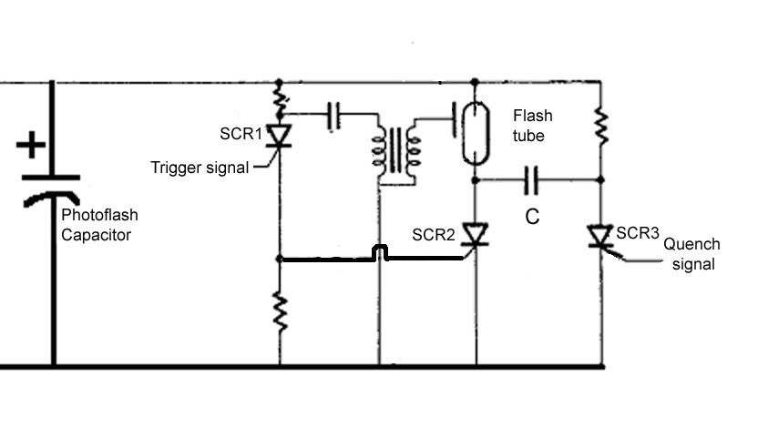
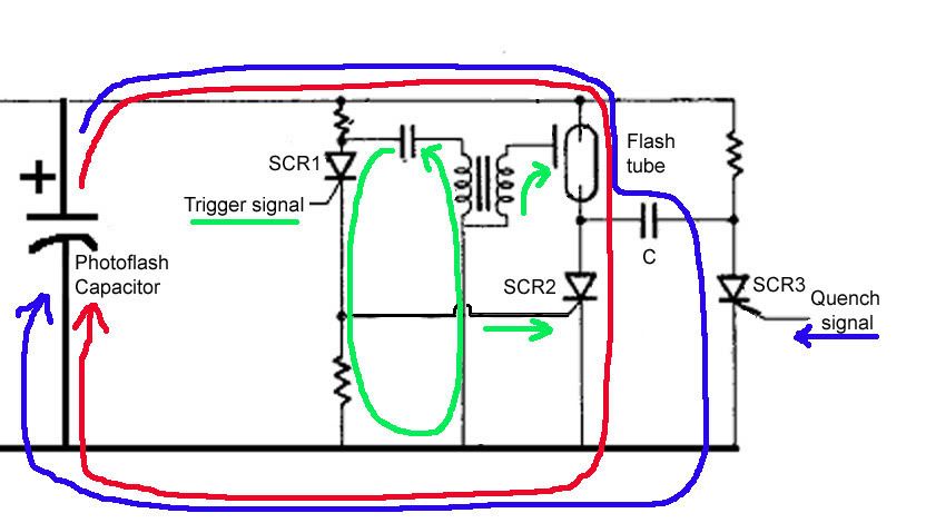
This schematic shows the typical complicated circuit of three SCRs needed in the auto-power-saving-thyristor flash unit. In actuality a high power strobe probably still uses this type of circuit. |
 This represents a modern flash block diagram. It does not show the receiver for signal from the camera, the control for the motorized Fresnel lens to set the zoom angle, the auto focus illumination assist beam, or other high end functions. |
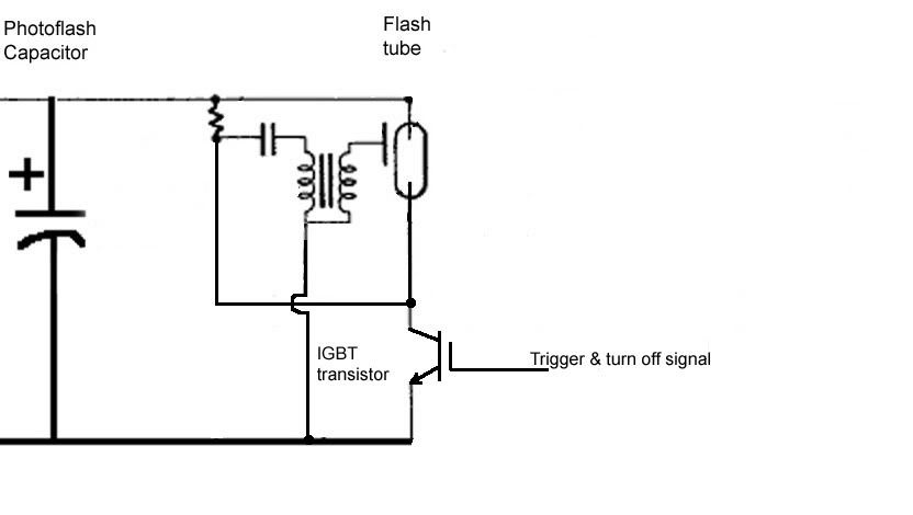
 This is a typical flash circuit using a Fairchild isolated gate bipolar transistor. Please note that IGBTs are not currently suitable for high power strobes. |
 This is a demo flash that Fairchild engineers built to demonstrate that their IGBT is suitable for a photographic strobe use. Note that at 290 μF the maximum strobe energy is 12 watt-seconds, and is is more likely 9 watt-seconds. This is not much more energy than one of the built-in strobes in the camera body. It is definitely a lightweight. |
How an SCR is quenched.

| The circuit to safely fire an older flash unit. If you have
an old flash unit with a high current, high voltage trigger circuit, you
need to protect your camera's synch circuit. This is a highly refined
circuit that will protect your camera no matter what flash you connect
to it. It can be battery powered if needed, or powered from the flash
trigger circuits. You must determine the polarity of the flash unit
first.
|
| Typical inverter to get high voltage from a low voltage battery
|
| Voltage Doubler - about 300 V
|
| Voltage tripler - about 450 volts
|
From Doug Smith
http://home.comcast.net/~dougsmit/bounceflashtoys.html
http://photocamel.com/forum/lighting-technique/29010-home-made-flash-bracket.html
http://photocamel.com/forum/lighting-technique/29713-flash-diffusers-cheaper-answers.html


 Direct |
 Bounce |
 Cut |
 Solid |
 BBQ |
 Syrup |
 Paper |
 Bubble |
Direct: Direct flash on camera
Bounce: Bounce flash no diffuser
Cut: Milky plastic diffuser with bottom removed (baby juice bottle)
Solid: Milky plastic diffuser with bottom intact (baby juice bottle)
BBQ: Clear, thin plastic bottle (Barbecue sauce bottle)
Syrup: Clear bottle with silver reflector on back (Pancake syrup bottle)
Paper: Plain white paper reflector behind flash
Bubble: Bubble wrap bag
Except for the direct flash image, all were taken with the flash head
pointed up.
I own NO commercial diffuser so I can't answer how this test would differ if
it included a Fong or Omnibounce. My total expense on the project is less
than either of the above and I got the contents of these bottles as a bonus.
I learned a lot in the process. I would love to see someone post a similar
series using all of the commercial units.
Overall my favorite is the baby juice bottle but I flop back and forth
between the cut and uncut one according to the subject. I should have done
these in portrait mode to make the shadows more evident.
Solid (left) Cut(right)

Both shown here were made from plastic bottles that once contained Delmonte brand baby apple juice. They are soft plastic and milky. Properly cut, they slide easily over the flash head and get rotated 90 degrees to hold firmly in place. One (on the ball head) also had the bottom of the bottle cut out so more of the flash escapes upward to bounce off of the ceiling. This works better in a room with a white ceiling. The bottle (on camera) with the bottom intact throws more light (in proportion) forward and can cause more of a shadow behind the subject but it works better if the ceiling is not good for bouncing.
Syrup

The diffuser shown on the macro rig [...] is very specialized made from a clear (pancake syrup) bottle with a piece of silver tape on one side to throw more light down on the nearby subject. It wastes a lot of light but softens the shadows compared to direct flash. It was made just before I shot the image so it happened to be on the flash at that time. I'm not sure it offers any advantage over the plain bottles shown on my page. Part of the 'game' is trying enough things to see which have merit and which are 'also ran'. Any diffuser (including the $50 commercial ones) give better results than direct flash.
Bubble

Paper

Milk (left) BBQ (center and right)

Universal Bounce Diffuser

This type of diffuser does nothing but bounce some light off the walls and allow some to go to the subject. If the walls were painted black, its only effect would be to reduce the brightness of the flash.

Here I am using a diffuser that I got designed by Gary Fong, but, it does little more than a Universal diffuser. It seems to be more efficient than the milky plastic type, but I have not done any real tests to see.


I also found these same items in the Spiratone 1991 Studio Lighting Catalog, under the name " air-flector" for $14.95
 |
 Direct
builtiin flash on the camera body. Direct
builtiin flash on the camera body. |
 |
 Direct
flash handle mount ("potato masher") Direct
flash handle mount ("potato masher") |
 |
 Direct
flash with wide angle diffuser Direct
flash with wide angle diffuser |
 |
 Bounced
flash, 45 degress up to ceiling, no swivel. Bounced
flash, 45 degress up to ceiling, no swivel. |
 |
 Bounced
flash to ceiling. 45 degrees up and swiveled 90 degrees to the left. Bounced
flash to ceiling. 45 degrees up and swiveled 90 degrees to the left. |
 |
 Bounced
flash to ceiling. 45 degrees up and swiveled 90 degrees to the left with
flip-it card. Bounced
flash to ceiling. 45 degrees up and swiveled 90 degrees to the left with
flip-it card. |
|
|
 Bounced
flash to ceiling. 45 degrees up and swiveled 90 degrees to the left with
flip-it card. Card intercepting minimal light. Bounced
flash to ceiling. 45 degrees up and swiveled 90 degrees to the left with
flip-it card. Card intercepting minimal light. |
 |
Bounced
flash to ceiling. 45 degrees up and swiveled 90 degrees to the left with
flip-it card and flip-it diffuser. |
 |
 Home
made giant bounce card Home
made giant bounce card |


